![]()
ESPShell includes ability to generate a squarewave signal on any pin with user configurable frequency and duty cycle. Frequency can be set from 1Hz up to 10 MHz with duty cycle ranging from 0 (=0%) to 1 (=100%). Default value for the duty cycle is 0.5 which means 50% duty cycle. LEDC driver is used for this squarewave generator.
Minimum and maximum frequencies which can be achieved with ESP32's PWM depend on many factors and can not be precisely stated here. ESP32 can go down to 1 Hz, while ESP32S3 low limit is higher.
Although ESP32S3 chip has 8 PWM channels but only 4 timers so it is 4 different frequences can be generated at the same time through 4 different pins. It is little better with basic ESP32 which has 16 channels thus allowing for 8 frequencies.
There are 4 commands that are used to start/stop PWM generation, change some settings and displaying information:
Command "pwm" starts a squarewave output on given pin:
esp32#>pwm 2 1000
The command above starts a 1 kHz squarewave on pin 2 (duty cycle is 50%) It is not blocking command, so it is not necessary to use "&" option to the command (see background execution): it executes in a background by default.
The duty cycle parameter can be set as third argument to the "pwm" command: lets set frequency on pin 2 to 5000Hz, duty cycle around 30%:
esp32#>pwm 2 5000 0.3
To stop a squarewave generator on given pin use "pwm" command with just one parameter. Example below shows how to stop squarewave generation on pin 2
esp32#>pwm 2
Setting frequency to 0 Hz or using a keyword "off" in place of frequency will have the same effect: disabling PWM on pin. Three commands below are equivalent:
  esp32#>pwm 2
  esp32#>pwm 2 0
  esp32#>pwm 2 off
One important thing to consider is the duty cycle resolution. Although ESPShell expects a floating point number as a duty cycle (e.g. 0.721), the hardware has its limits: the higher the PWM frequency is the less precise we can set a duty cycle. For example, 1000 Hz frequency generator has 14 bit precision for its duty cycle. That means, the duty cycle can be anything from zero to 2^14-1. With frequency of 10MHz we have only 3 bits to represent our duty cycle..
ESPShell selects best available duty cycle precision (resolution) for given frequency. This default behaviour however, can be overriden with "var ledc_res" command: being set to a positive value it overrides calculated duty resolution.
Example:
esp32#>var ledc_res 8
The command above sets PWM duty cycle resolution to 8 bits. Attempt to start 10Mhz PWM will fail in this case
ESP32 has 16 (while ESP32S3 has 8) so-called LEDC (PWM) channels. Adjacent channels (i.e. channel0 and channel1 or channel6 and channel7) share same timer thus not able to generate 2 different frequencies: instead, changing channel frequency immediately changes frequency on its adjacent channel.
Because of this, ESPShell selects only **even** channel numbers for its operation. Doing so guarantees that every other PWM output has its unique frequency; however it reduces the number of available channels: instead of 8 only 4 are available on ESP32S3.
For many PWM applications involving many PWM outputs, the frequency is usually the same, while duty cycle can vary: one of such example is a multiple led strips. Multiple-output regulated power inverter is the another example.
In such cases ESPShell can be set to use both odd and even numbers so all available channels can be used (up to 16 on original ESP32): this is done by executing "var pwm_ch_inc 1" shell command.
Additionally one can manually set hardware channel number to use. In most cases we don't need to specify this channel number: it is autoselected by cycling through numbers 0, 2, 4, ...; Shell uses simple formula to select channels to use:
Channel_To_Use_Next_Time = Current_Channel + "var pwm_ch_inc"
Below is the command to enable 1kHz 50% duty PWM on pin1, using hardware channel 2:
esp32#>pwm 1 1000 0.5 2 < --- 4th argument is a channel numberDoing so results in altering internal espshell channel counter:
  esp32#>pwm 2 1000 0.5 5
  % PWM on pin#2, 1000 Hz (0.5% duty cycle, channel#5) is enabled
  % PWM channel 7 is to be used next, if not explicitly set
Channel #7 was selected because of pwm_ch_inc default value which is 2. Lets look at example below to see how changing this variable affects channel selection behaviour:
  esp32#>pwm 2 1000 0.5 5
  % PWM on pin#2, 1000 Hz (0.5% duty cycle, channel#5) is enabled
  % PWM channel 7 is to be used next, if not explicitly set         < -- channel 7

  esp32#>var pwm_ch_inc 1

  esp32#>pwm 2 1000 0.5 5
  % PWM on pin#2, 1000 Hz (0.5% duty cycle, channel#5) is enabled
  % PWM channel 6 is to be used next, if not explicitly set        < -- channel 6
Setting "pwm_ch_inc "to 0 will prevent channel number from changing (unless /channel/ argument is used)
To display status & parameters of PWM signals there is a dedicated "show" command:
| show pwm | Displays current state of all PWM sources |
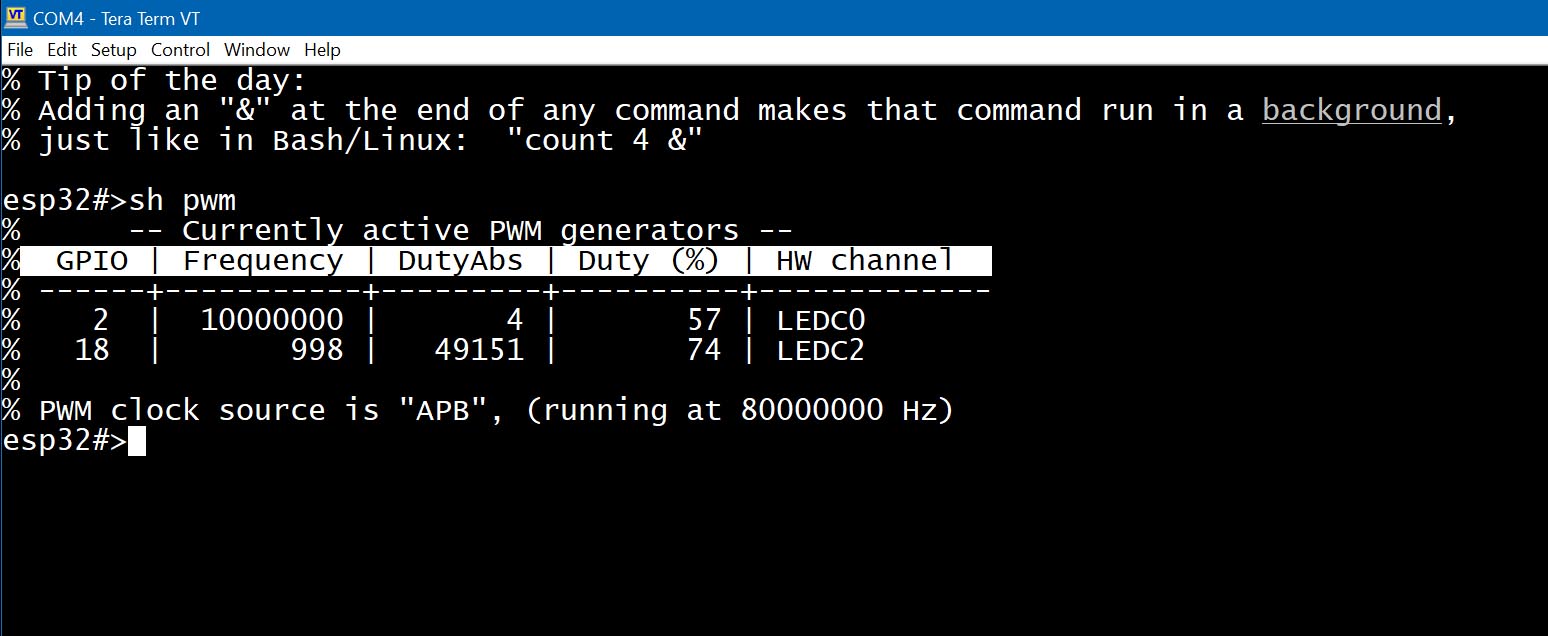
Fig. 2: Example output of "show pwm" command
Table above says that pin#2 is active PWM source, 10MHz, 57% duty cycle; Although it was set to 50% by command "pwm 2 10000000 0.5", limitations of the hardware only allow 3 bits as the duty value, so it can be set only approximately; Pin 18 is a PWM source too, with frequency of 1KHz and duty cycle of 75%.
DutyAbs is the absolute duty cycle value, which depends on duty % and duty resolution parameters; Other columns carry pin numbers, frequencies and a hardware channel number used.